
Since 2015
Custom battery pack projects
5,000 m²
Own factory
6 engineers
15+ years’ professional experience
60
Production-line employees
25+ countries
Traded with customers in
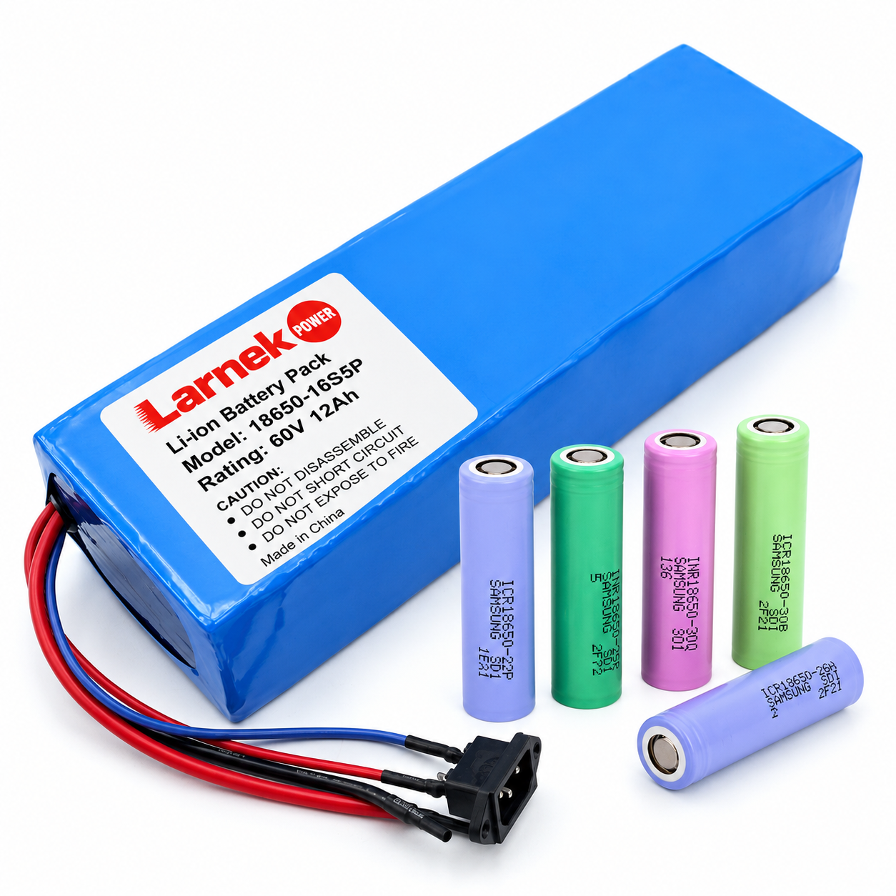
What Makes a Battery Pack Industrial?
An industrial battery pack is a battery assembly built for professional equipment rather than consumer devices. It is sized for a defined duty cycle and service life, designed for the equipment’s temperature and vibration, connected through a fixed mechanical and electrical interface, and supplied to a locked specification for as long as the equipment is produced.
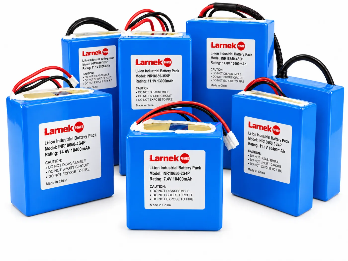
Most battery pack systems for industrial devices use the same lithium-ion cells as other products. What changes is what the pack is designed against. The table shows where a pack built for your equipment differs from a catalogue pack chosen by voltage and capacity alone.
|
Design point
|
Catalogue pack
|
Industrial pack for your equipment
|
|---|---|---|
|
Sizing basis |
Rated capacity on day one |
Runtime needed at end of service life, at your coldest operating temperature |
|
Environment |
Room temperature assumed |
Your operating and charging temperatures, vibration, dust and moisture |
|
Mechanics |
Standard shape, loose leads |
Your envelope, mounting points, cable exit and locking connector |
|
Electronics |
Generic protection board |
BMS limits, temperature sensing and signals matched to your charger and controller |
|
Service |
Replaced as a whole product |
Fixed or field-replaceable, decided at the design stage |
|
Supply |
Cells or board may change between batches |
Cell model, BMS settings and build specification fixed for repeat orders |
Cell-format choice (18650 or 21700) comes after these points. See 18650 battery packs and 21700 battery packs for format-specific design.
Sizing an Industrial Battery Pack for the Last Shift, Not the First
A pack that just covers a shift when new will not cover it after a few hundred cycles or on a cold morning. We size industrial packs from the energy your equipment uses, then add margins for ageing and temperature before choosing the series-parallel configuration.
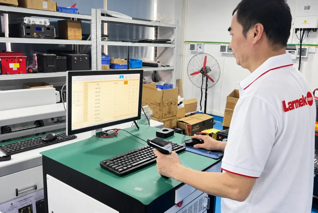
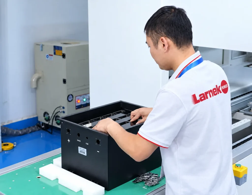

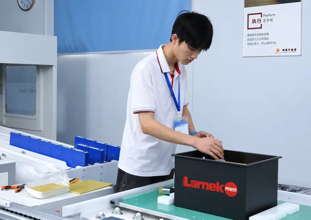
1. Energy per shift
Average power × working hours between charges. Measured logs beat estimates.
2. End-of-life margin
Divide by the share of capacity the pack must still have when it is due for replacement – often 80%.
3. Temperature margin
Allow for less usable energy at your lowest operating temperature, taken from the cell data.
4. Series and parallel count
Series count from your device’s voltage window, parallel count from the capacity left to find. The voltage classes are listed on our 18650 battery pack page.
5. Current and shipping check
Confirm current per cell against peaks (see 21700 battery packs) and note whether the pack exceeds 100 Wh for transport.
Energy budget for the worked example
Energy per shift: 120 Wh
+ end-of-life: 150 Wh
+ cold margin: ≈167 Wh
Chosen pack: 172.8 Wh · 4S · 12 Ah
Worked example: 15 W average, 8-hour shift, 12–16.8 V input
|
Option
|
Cells
|
Config.
|
Rated
|
Runtime new
|
Runtime at end of life, cold
|
|---|---|---|---|---|---|
|
18650, 3.0 Ah example cell |
16 |
4S4P |
12 Ah · 172.8 Wh |
11.5 h |
8.3 h ✓ |
|
21700, 4.0 Ah example cell |
12 |
4S3P |
12 Ah · 172.8 Wh |
11.5 h |
8.3 h ✓ |
|
18650 4S3P (day-one sizing) |
12 |
4S3P |
9 Ah · 129.6 Wh |
8.6 h |
6.2 h ✗ |
4S = 14.4 V nominal (3.6 V per cell). End-of-life taken as 80% of rated capacity; cold margin as 10% less usable energy. Both factors are illustrative – we use the figures for your cell and temperature range. Example cells, not a cell recommendation.
What the example shows: sizing on day-one capacity picks a pack that loses two hours of the shift by the end of its life. Both correct options are above 100 Wh, which affects transport testing and shipping documents – see testing, certification and compliance.
Operating Conditions That Change an Industrial Pack’s Design
Tell us where the equipment works and where it is charged. Each condition below changes something specific in the pack, so we fix it in the specification before samples are built.
Cold operation and charging
Effect: Cells deliver less energy in the cold, and most lithium-ion cell datasheets do not allow charging below about 0 °C.
We specify: Capacity for your coldest working temperature, and BMS charge-temperature limits. If charging happens in unheated areas, tell us early.
Mechanical Integration: Mounting, Envelope and Service Access
The first integration decision is how the pack will be serviced. It changes the enclosure, the connector and what the operator is allowed to touch, so we settle it before the layout.
Fixed pack
Installed at assembly and replaced by a technician, if ever.
- Mounted with brackets or fixing points in your frame
- Harness routed and clamped to your drawing
- Compartment can provide part of the protection
Field-replaceable pack
Removed and swapped by operators, sometimes several times a day.
- Protective housing that can be handled and dropped
- Connector rated for repeated mating, keyed against wrong insertion
- Charging inside or outside the machine – affects interface
- Envelope: maximum size including holders, insulation and clearances – layout options on our 18650 battery pack page
- Weight and centre of mass where the pack sits on a moving or handheld machine
- Cable exit and length so leads are not bent or pulled at the pack
- Connector type, keying, latch and pin-out
- Label position readable after installation
- Mounting tolerances agreed on a drawing before samples
More on structure and assembly: battery pack design and assembly.
BMS and Interfaces Between the Pack and Your Equipment
Every industrial pack has a BMS for over-charge, over-discharge, over-current, short-circuit and temperature protection. What varies is how the pack talks to the equipment and its charger – and that has to be fixed in the pin-out early.
Illustrative only. The real pin-out is agreed per project and drawn on the pack specification.
|
Interface point
|
What we need from you
|
Why it matters
|
|---|---|---|
|
Charger |
Charger model, or required charge voltage and current |
Charge voltage follows series count – 16.8 V for a 4S pack of 4.2 V cells. Lead-acid chargers are not suitable for lithium-ion packs. |
|
Protection limits |
Continuous and peak load, start-up surges |
Over-current limits that trip on motor start-up stop the machine; limits that are too loose stop protecting it. |
|
Temperature signal |
Does your charger or controller read a thermistor? Which type? |
Lets the charger stop outside the safe temperature window. |
|
Battery data |
Whether the controller needs state of charge or fault data, and over which protocol |
Communication is specified per project and confirmed against your controller. |
|
Enable / ID |
Any wake-up, enable or pack-identification line |
Prevents the equipment starting on the wrong pack and helps service teams. |
BMS selection and settings in more depth: BMS integration.
Battery Packs for Industrial Devices, Grouped by How They Work
The same voltage can hide very different jobs. We group industrial equipment by its duty pattern, because that decides which margin dominates the pack design.
Runs for hours under steady load
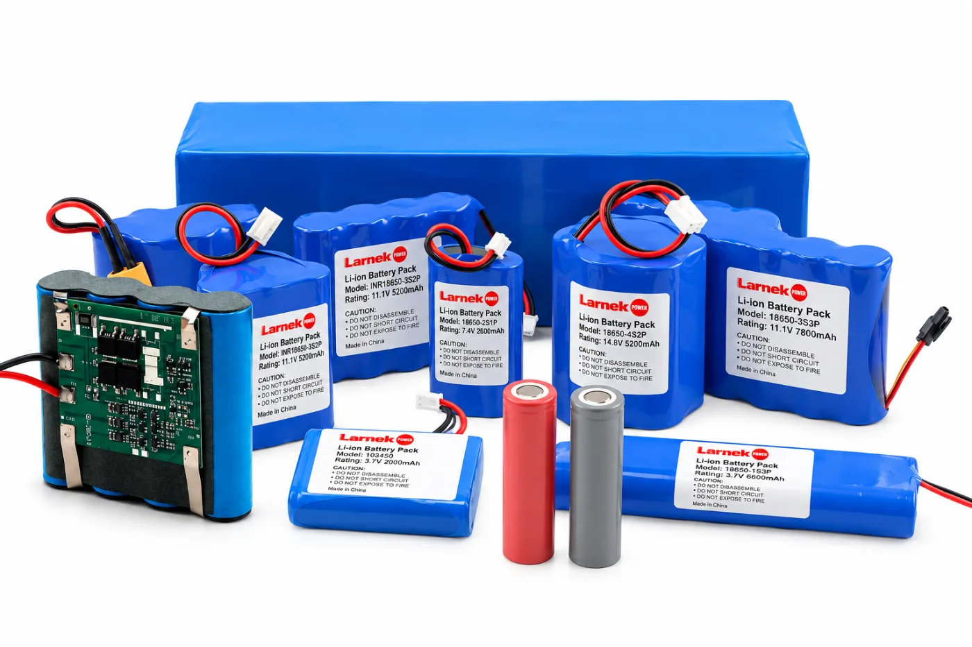
Industrial equipment · Cleaning equipment
End-of-life runtime dominates. Where lithium replaces lead-acid, the voltage window and charger have to be matched, not just the capacity.
Low base load with sharp peaks
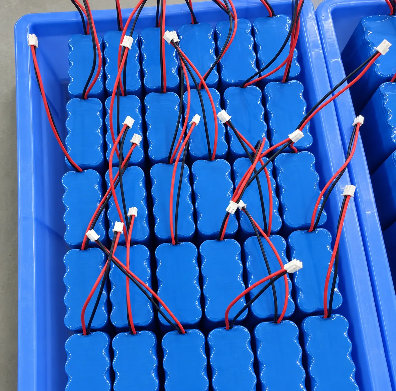
Communication equipment · Portable power equipment
Peak current and voltage sag dominate: parallel count and protection limits are set by the peak, not the average.
Waits for months, then must work
Emergency lighting · Remote monitoring systems
Self-discharge, BMS standby drain and site temperature dominate. Long visit intervals make reliability more valuable than peak energy.

Carried, dropped, used outdoors
Portable instruments · Inspection & measurement devices
Weight, housing strength and stable voltage through discharge dominate, so readings stay repeatable.
Your machine fits none of these patterns? Tell us how it is used in the brief below, or browse applications. For projects outside equipment use, start with our custom battery packs overview.
Long-Term Supply: One Locked Build for Every Repeat Order
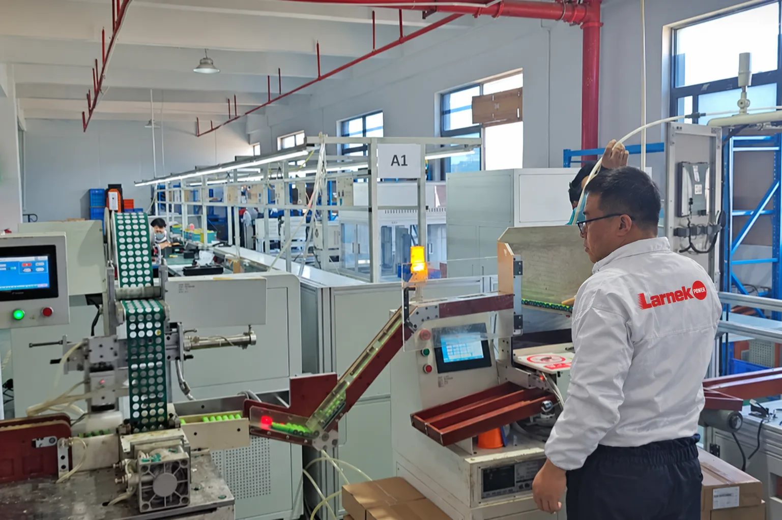
Industrial equipment is often produced and serviced for years. A replacement pack bought in year five has to fit, connect and behave like the one approved at launch, so we treat the approved sample as a specification, not a starting point.
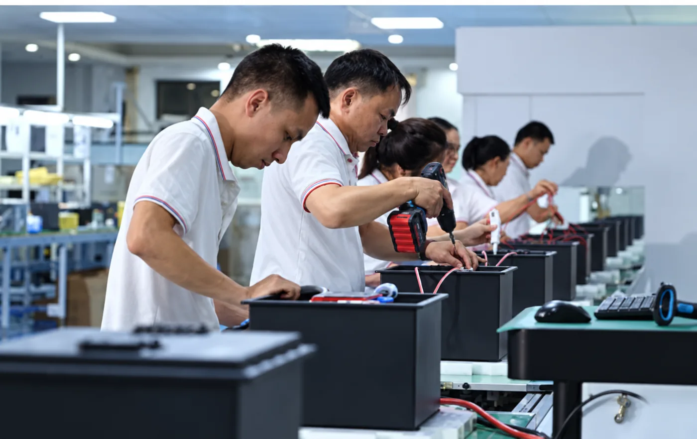
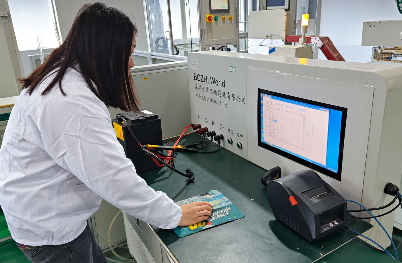
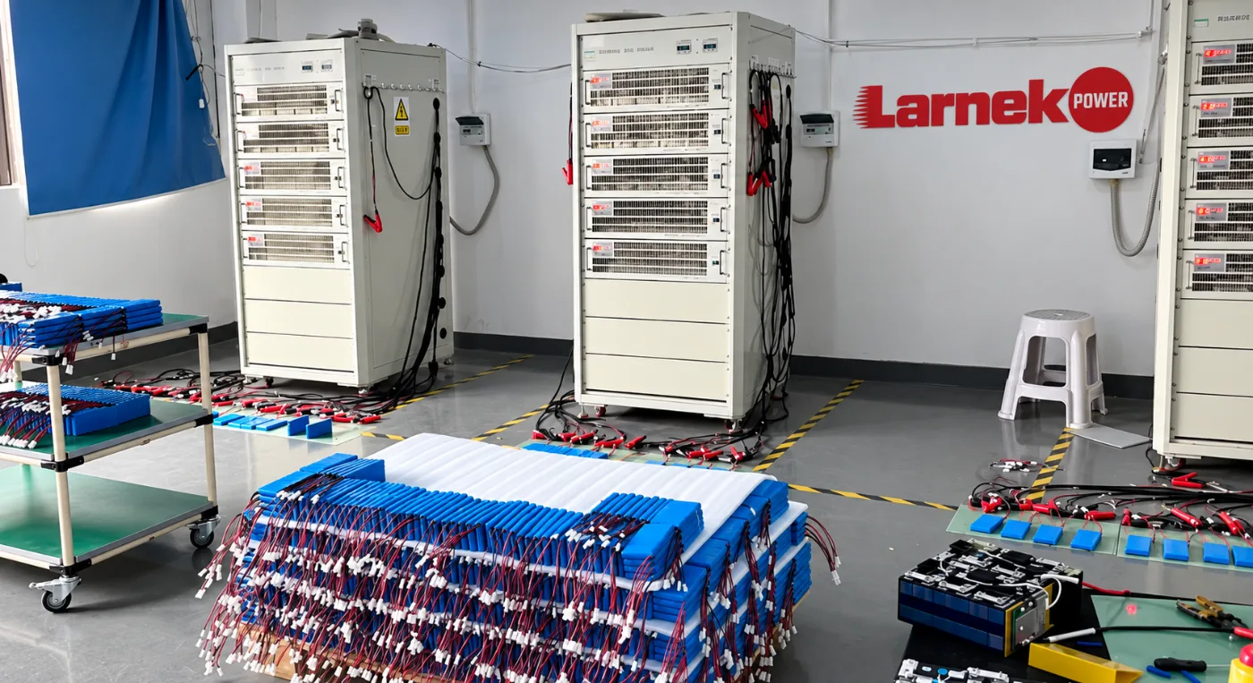
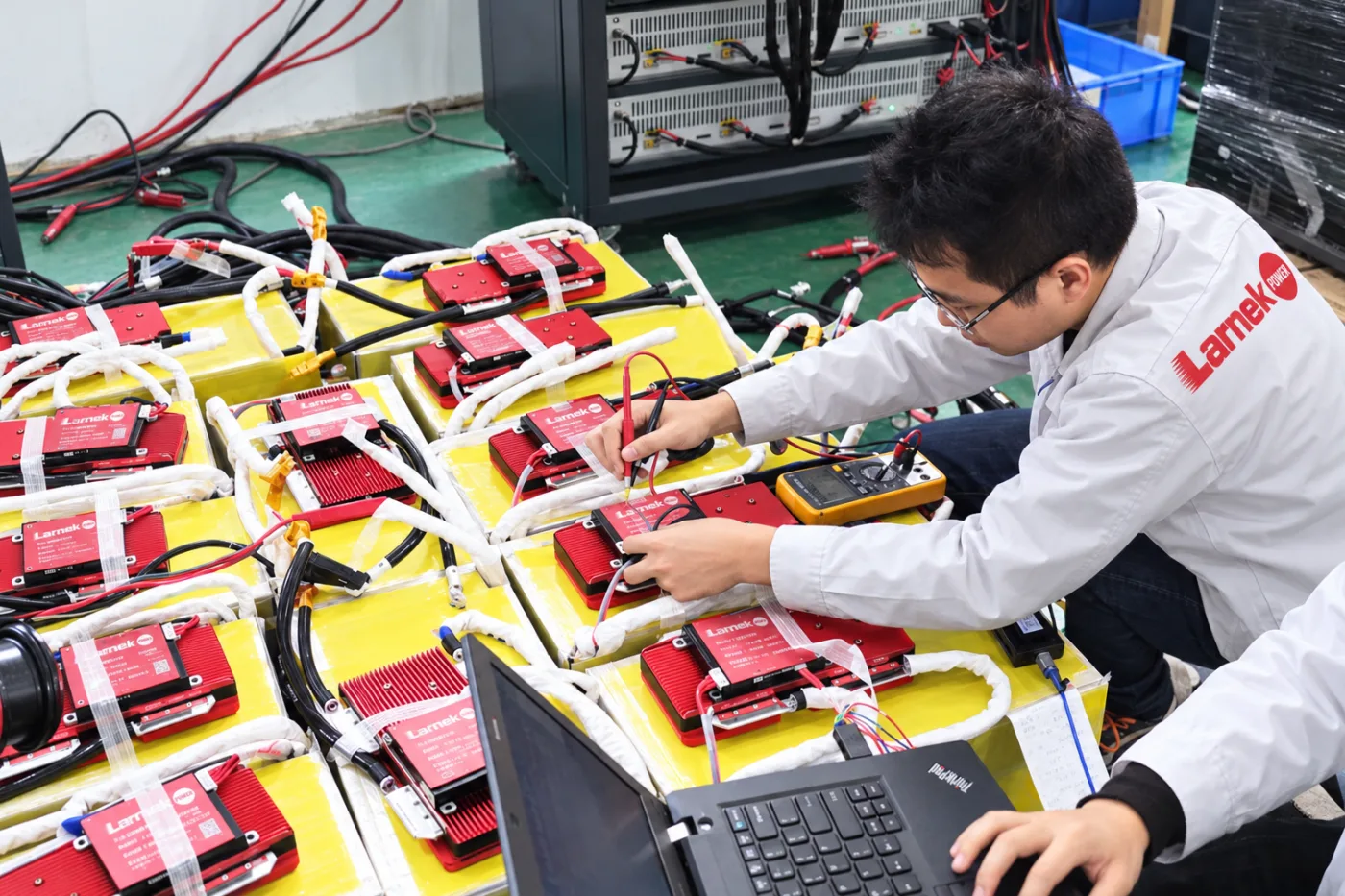
Behind the build: Larnek Power is an industrial battery pack manufacturer with its own 5,000 m² factory, six engineers with more than 15 years of experience and 60 production-line employees, supporting projects since 2015 and trading with customers in over 25 countries. See how a project runs from requirements to volume on our OEM & ODM battery pack development page, or meet the custom battery pack manufacturer.
Describe Your Equipment and Its Duty Cycle
For an industrial battery pack, how the machine is used tells us more than a target capacity. If you are replacing a battery in existing equipment, three things are enough to begin:
- Photo of the current battery’s label, connector and compartment
- Hours of use per shift or between charges
- Coldest and hottest temperatures where it works and charges
Your Battery Pack, Built Safe, Compliant and On Time
Backed by a strong Shenzhen supply chain, a dedicated engineering team and hands-on export experience, Larnek Power helps OEM teams move custom battery packs into production with consistent quality, competitive cost and the paperwork export requires.
Tell Us About Your Battery Project
Larnek Power supports OEM and industrial customers with custom 18650 and 21700 lithium-ion battery packs, from initial requirements and prototyping through volume production.
Tell us about your application, target voltage and capacity, size limits, current requirements, estimated quantity, and any drawings or existing battery details. Our engineering team will review your requirements and help define the next steps for your project.